X-, Y-, and Z-Axes
This section describes the directions that parts of the printer move in. The directions are similar to the way you move your hand, for example, when you use a 3D pen. If you move your hand back and forth to the left and to the right in front of you, we call that motion in the x-direction. If you imagine a number line in front of you that extends to the right and left, then that number line would be called the X-Axis.
If instead of moving your hand back and forth to the left and right, you moved your hand back and forth away from you and toward you, we call that motion in the y-direction. If you imagine a number line in that direction extending away from you and toward you then that number line would be called the Y-Axis.
Finally, if you move your hand up and down in front of you in a straight line, we call that motion in the z-direction. A number line extending in the up and down directions would be called the Z-Axis.
The 3D printer uses these same directions, and certain parts of the 3D printer move in those directions. The picture below shows the Heat Bed platform with the Metal Plate put back in place, and above it can be seen the arm that the Hot End and fans are attached to.
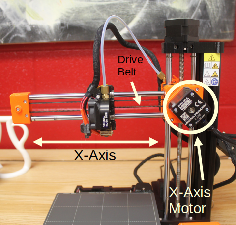
Notice the white double-ended arrow labeled X-Axis. This double arrow indicates the direction that the Hot End and fans can move along the arm sticking out over the metal plate. This motion is in the x-direction. Thus, it is called the X-Axis. This motion is produced by the X-Axis Motor, indicated in the picture by the white circle. A rotating rod sticks out of the motor and is attached to the Drive Belt. The Drive Belt is also shown in the picture, and looks like a long rubber band with small teeth. The Hot End and fans are connected to the Drive Belt, and slide along the metal rods in the x-direction as the motor moves the Drive Belt.
The next picture shows the Heat Bed with the Metal Plate attached.
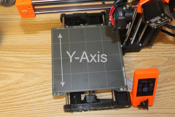
Notice the white double-ended arrow labeled Y-Axis. This arrow represents the two directions that the entire Heat Bed-Metal Plate platform can move in. Since motion in this direction would be in the y-direction, this is called the Y-Axis. As indicated, there are two possible ways the Heat Bed-Metal Plate platform can move: 1) the platform can move away from you as you’re facing the 3D printer, or 2) toward you as you’re facing the 3D printer.
The next picture shows a close-up of the top of the Metal Plate and also a close-up of the Y-Axis Motor and part of the Y-Axis Drive Belt.
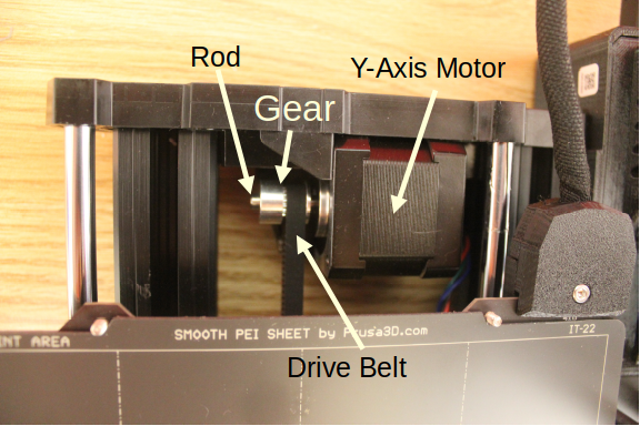
You can see the rod sticking out of the Y-Axis Motor and the Gear attached to it. The Y-Axis Drive Belt is attached to this Gear. That is why the Drive Belt has the little teeth that grab onto the slots in the Gear. The Drive Belt is also attached to the bottom of the Heat Bed. The Y-Axis Motor is thus able to move the entire platform back and forth along the Y-Axis depending on which way the motor turns.
The next picture shows the top of the 3D printer. The black cube on top is another motor, the Z-Axis Motor.
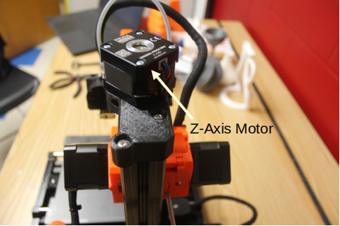
This motor is responsible for moving the entire arm that sticks out over the Metal Plate up and down. This can be seen in the next picture.
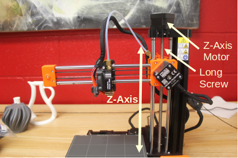
The double ended arrow indicates motion in the z-direction. Thus, this is called the Z-Axis. The Z-Axis Motor moves the entire arm up and down along the Z-Axis. A rod sticking out of the Z-Axis motor is attached to a thicker rod that looks like a Long Screw. This Long Screw can be seen up close in the next picture.
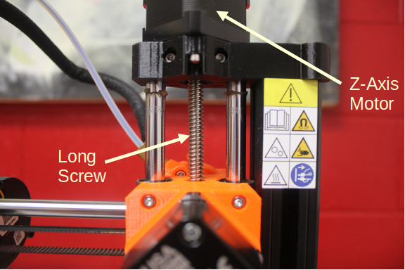
Motion along the Z-Axis is done differently from the way motion in the x- and y-directions is produced. You saw earlier how the Hot End and fans are moved along the arm in the x-direction and how the Heat Bed-Metal Plate platform is moved back and forth along the y-direction. Both of those movements are produced by a Drive Belt connected to the motors. The z-direction motion is achieved by turning the Long Screw.
The spiral grooves in the Long Screw are are called threads. When the long threaded rod (the Long Screw) is turned by the Z-Axis Motor, the X-Axis arm is able to move up and down, depending on which way the Z-Axis Motor is turning. Using a threaded rod (that’s a fancy way to say a Long Screw) allows us to more accurately control the position of the Nozzle where the plastic is pushed out than we could control the position just using a Drive Belt. This ability to accurately control the location of the printer Nozzle in the z-direction is very important for producing good 3D prints.
All this talk about axes and directions may remind you of something you studied in your math classes. The X-Axis, Y-Axis, and Z-Axis are the same as the different number lines you learned about in math class. All three of these Axes, X, Y, and Z, together make up what is called a coordinate system. Yes, all of that math stuff is indeed useful. In the case of a 3D printer, axes and directions are very important for communicating with the 3D printer and ensuring that the plastic is pushed out at the right place at the right time.